http://37.59.39.49/failid/audiclub/a4s4b5clusterpinouts.html
A4/S4 B5 Instrument Cluster Pin Outs
Leave a reply
http://37.59.39.49/failid/audiclub/a4s4b5clusterpinouts.html
DIESEL
Part Number Maximum Speed Mounted Dice Color Clock
From Analog clock
8D0 919 034 E 220 KM / H to 96 2x26pinowa and 1x20pinowa
8D0 919 036 A 135 MPH to 96 2x26pinowa and 1x20pinowa
8D0 919 033 N 220 KM / H to 96 2x26pinowa and 1x20pinowa
8D0 919 035 L 135 MPH to 96 2x26pinowa and 1x20pinowa
8D0 919 034 220 KM / H to 96 2x26pinowa and 1x20pinowa
8D0 919 035 Q 135 MPH to 96 2x26pinowa and 1x20pinowa
From Analog clock
8D0 919 880 M 260 KM / H to 98 2x32pinowa and 1x20pinowa
8D0 919 881 A 260 KM / H to 98 2x32pinowa and 1x20pinowa Light Gray
8D0 919 930 H 160 MPH to 98 2x32pinowa and 1x20pinowa
8D0 919 880 D 260 KM / H to 98 2x32pinowa and 1x20pinowa
8D0 919 930 D 160 MPH to 98 2x32pinowa and 1x20pinowa
8D0 919 881 H 260 KM / H to 99 2x32pinowa and 1x20pinowa
8D0 919 881 R 260 KM / H to 99 2x32pinowa and 1x20pinowa
8D0 919 930 M 160 MPH to 99 2x32pinowa and 1x20pinowa
From Digital clock
8D0 920 980 J 160 MPH to 01 3x32pinowa CAN-Bus
8D0 920 980 M 160 MPH to 01 3x32pinowa CAN-Bus
8D0 920 932 F 260 KM / H 00 3x32pinowa CAN-Bus
With a watch Radiowym
8D0 920 931 T 260 KM / H 00 3x32pinowa CAN-Bus
8D0 920 932 C 260 KM / H 00 3x32pinowa CAN-Bus Gray
Disclaimer. The information on this post is for informational purposes only.
This post and all of the information it contains are provided ‘as is’ without warranty of any kind, whether express or implied.
The wiring information was taken from “Bentley Publishers CD and Hardcover copy”, there may be omissions or inaccuracies in information contained in this post. Before making any decision or taking any action based on the information contained in this Post, you should double/triple check information regards to the vehicle you service.
If you found that the information is inaccurate and you have found the solution post it up and I will update the post.
*updated May 01, 2012* additional information provided by MetalMan
Couple people ask me if I can show the difference between instrument clusters from 1996 to 2001.5
The photo below shows all 3 instrument clusters from 1996 to 2001.5 with Full size LCD, some models didn’t come with LCD screen because of the package was not selected during order back then.

Here is the back of the instrument clusters.

You can see the difference between all the clusters the cluster 1 is CDN or European but MPH is identical except speedometer is in MPH the other two are MPH clusters I had,
Cluster 1 was installed in 1996 and 1997 Audi A4 early models , no immobilizer the most visible difference is if you look at the analog clock has no digits at 3, 6, 9, at 12 o’clock comparing to cluster 2
Cluster 2 was installed in 1998 to 1999.5 Audi A4 models, , you could swap cluster between these years with no issues, no immobilizer.
Cluster 3 was installed in 2000 to 2001.5 Audi A4 models,some 99.5’s with VIN > 8DY000001 had cluster with digital clock, the main difference was the analog clock was replaced with digital clock to match the mileage LCD, and in late 2001 immobilizer was added to system
NOW COMPATIBILITY
Legend
Cluster 2, and cluster 3 can not fit directly into cluster 1, because cluster 1 has different plugs , in order to fit you need to buy new plugs and new pins and rewire some connection.,
I know two people who proceed with this conversion one did the cluster 2 to cluster 1 and had partially working cluster,
all the gauges were working however compatibility was an issue and error code were reported cluster did not understand modules in the car, other did cluster 3 to cluster 1 and had only partial success two gauges were working , all the lights were lit up like Christmas tree .
Cluster 3 can be installed into cluster 2 however some rewiring is required to both blue and green plugs and the middle plug from cluster 3 doesn’t fit cluster 2 which you need to rewire as well,
regards to immobilizer on some early 2001 clusters this feature can not be disabled in the instrument cluster the little car key will flash some people cover it with electrical tape, but it will beep at start up for 3 seconds.
Also Can Bus was introduced in some early 2000+ models which meant that vehicle in 1998-1999 didn’t have can-bus and some clusters from 2001-2001.5 didn’t work the tachometer or speedometer was not functional
If you really want to have digital clock in 1998-1999 A4 model try to get 1999.5 to 2000 instrument cluster that don’t have immobilizer or Can-Bus requirement.
Cluster 3 with immobilizer will work in early cluster 3 however immobilizer light will be present during start and will flash continuously and it will beep for 3 seconds during start up.
If your car came originally without center LCD , you can swap the cluster with LCD however in order to change menus you need to buy new wiper arm with switch and wiring and add wires between the cluster and wiper arm

you will need the wiper control arm that has a switch at the end wiper arm to change menus on center LCD

for 1996 to 1997 Cluster 1
you need wiper arm
part# 8D9 953 503 A (sedan)
part# 8D9 953 503 C (Avant)
for 1998 to 2001.5 Cluster 2, and Cluster 3
Part# 4D0 953 503 B (sedan)
part# 8D0 953 503 D (Avant)
There are 3/4 sets of wires required for wiper arm control harness plug and for the instrument cluster harness plug for the Grey Connector on
Cluster 3, and red connector of Cluster 2 , black connector on cluster 1
I recommend to buy wires from Audi/VW dealer
On cluster 1
You need to insert wires into black 20 pin connector on instrument cluster and to 6 pin harness plug on the wiper arm
Black connector Pin 11 to wiper arm pin 1
Black connector Pin 14 to wiper arm pin 3
Black connector Pin 18 to wiper arm pin 4
Pin 2 on the wiper arm is ground
Pins 5, 6 are not used
On cluster 2
-added a wire between the longer ECU connector, pin 17 (yellow wire), to pin 1 on the RED instrument cluster connector
-grounded pins 9, 16, 19 on the RED instrument cluster connector since I don’t need bulb out warnings or low washer fluid warning (this worked)
You need to insert wires into red 20 pin connector on instrument cluster and to 6 pin harness plug on the wiper arm
Red connector Pin 18 to wiper arm pin 1
Red connector Pin 14 to wiper arm pin 2
Red connector Pin 11 to wiper arm pin 4
Pin 3 on the wiper arm is ground , I just made a short segment and connected it to the wire coming off Pin 5
Pin 5: ground for the intermittent wiper selector on top of the wiper arm
Pin 6: feedback wire for position of the intermittent wiper selector
For people who have a no-LCD cluster, pins 5 and 6 on the wiper arm will already exist, and they are supposed to exist while using the LCD cluster too. They should not be removed.
Cluster 3
you need to insert wires into Grey connector on the instrument cluster and to 6 pin harness plug on the wiper arm
Grey Connector pin 17 to wiper arm pin 4
Grey Connector pin 18 to wiper arm pin 3
Grey Connector pin 19 to wiper arm pin 1
Pin 2 on the wiper arm is ground
Pins 5, 6 are not used
How do I know if my cluster has immobilizer ?

Answer regards Color LCD

Here are Pin out for clusters with Full Size LCD
cluster 1
26-Pin Connector, Blue
1 – Open
2 – Signal for buzzer
3 – Terminal 15
4 – Terminal 15
5 – Open
6 – Terminal 61
7 – Parking brake/brake system malfunction
8 – ABS (input signal)
9 – Airbag (input signal)
10 – CAT
11 – Open
12 – Open
13 – Parking light, right
14 – Ignition switch, S-contact
15 – Chime signal
16 – Open
17 – Open
18 – Oil pressure 1.8 bar
19 – Terminal 58d
20 – Coolant level
21 – Turn signal, right
22 – Headlight high beams
23 – Speedometer Vehicle Speed Sensor (VSS) (checking → Chapter)
24 – Brake fluid
25 – Brake pads
26 – Parking light, left
26-Pin Connector, Yellow
1 – Terminal 58
2 – Terminal 58
3 – Engine RPM signal
4 – Air conditioner compressor
5 – Clock (output)
6 – Speed signal 1
7 – Speed signal 2
8 – Door contact (driver’s door)
9 – Terminal 30
10 – Terminal 30
11 – Open
12 – Fuel tank warning
13 – Turn signal, left
14 – Open
15 – Open
16 – Seat belt buckle switch
17 – Open
18 – Terminal 31
19 – Terminal 31
20 – Diagnostic wire
21 – Open
22 – Open
23 – Open
24 – Open
25 – Sender for fuel gauge
26 – Engine coolant temperature sensor
20-Pin Connector, Black
1 – Fuel consumption signal
2 – Open
3 – Open
4 – Open
5 – Outside air temperature
6 – Selector lever display
7 – Open
8 – Open
9 – Coolant level
10 – Hydraulic pressure
11 – Trip computer – Reset
12 – Radio/Telephone – Clock
13 – Radio/Telephone – Data
14 – Trip computer (forward sequence)
15 – Radio/Telephone – Enable
16 – Rear lights/headlight low beams
17 – Open
18 – Trip computer (reverse sequence)
19 – Brake lights
20 – Open
4-Pin Connector, Black
1 – Oil temperature sensor
2 – Open
3 – Open
4 – Open
cluster 2
32-Pin Connector for Basic Functions, Blue
1 – Terminal 15
2 – Turn signal, right
3 – Speedometer output 1
4 – Open
5 – Sender for fuel gauge
6 – Airbag
7 – Terminal 31 sensor Ground (GND)
8 – Coolant temperature
9 – Terminal 31 load Ground (GND)
10 – Oil pressure switch
11 – Engine speed (RPM) signal
12 – Terminal 61
13 – CAT
14 – Self leveling suspension
15 – Terminal 58d
16 – Malfunction Indicator Lamp (MIL)
17 – High beam
18 – Turn signal, left
19 – ABS
20 – Terminal 58s
21 – Door contact (driver’s door)
22 – Engine coolant low
23 – Terminal 30
24 – Terminal 31 load Ground (GND)
25 – K-wire
26 – Parking light, right
27 – Parking light, left
28 – Speedometer (input)
29 – Brake fluid level/pressure
30 – S-contact
31 – Seat belt buckle
32 – Electronic Stability Program (ESP)
32-Pin Connector for Additional Functions, Green
1 – Open
2 – Open
3 – Open
4 – Open
5 – W-wire
6 – Tailgate (Lowline model only)
7 – Brake pad (Highline model only)
8 – Input for outside buzzer control (currently not assigned)
9 – Input for outside chime control (currently not assigned)
10 – Low fuel level warning-output signal for Engine Control Module (ECM)
11 – Standing time output
12 – Air conditioning cutout
13 – Parking brake
14 – Electronic throttle
15 – Side marker light
16 – Open
17 – Open
18 – Open
19 – Open
20 – Open
21 – Oil temperature
22 – Open
23 – Open
24 – Open
25 – Open
26 – Open
27 – Open
28 – Open
29 – Open
30 – Speedometer output 2
31 – Open
32 – Open
20-Pin Connector for Multi-Function Display, Red
1 – Fuel consumption signal
2 – Open
3 – Open
4 – Open
5 – Outside air temperature
6 – Selector lever display
7 – Open
8 – Open
9 – Washer fluid
10 – Hydraulic pressure
11 – Trip computer reset
12 – Clock signal for radio frequency display
13 – Data signal for radio frequency display
14 – Trip computer (forward sequence)
15 – Enable signal for radio frequency display
16 – Tail lights/headlight low beam (indicator lights)
17 – Open
18 – Trip computer (reverse sequence)
19 – Brake lights
20 – Open
Cluster 3
Blue 32-Pin Multi-Pin Connector for Basic Functions
1 – Terminal 15
2 – Brake pad wear
3 – Tachometer output 1
4 – not occupied
5 – Tank sensor
6 – Tank warning OBD 2
7 – Terminal 31 (sensor Ground (GND))
8 – Coolant temperature
9 – Terminal 31 (load Ground (GND))
10 – Oil pressure 2 (high)
11 – RPM signal
12 – A/C shut-off
13 – E-Gas/glow plug control
14 – Level control
15 – Terminal 58d
16 – Trailer turn signal
17 – High beam
18 – Left turn signal
19 – not occupied
20 – Terminal 58s
21 – Driver door contact
22 – Low coolant
23 – Terminal 30
24 – Terminal 31 (load Ground (GND))
25 – Consumption signal
26 – Right parking light
27 – Left parking light
28 – Tachometer input
29 – Brake
30 – S-contact
31 – Tachometer output 2
32 – ESP/ASR
Green 32-Pin Multi-Pin Connector for Auxiliary Functions
1 – Door contact (all doors)
2 – Transponder 1
3 – not occupied
4 – not occupied
5 – W-wire
6 – Tailgate
7 – Right turn signal
8 – External buzzer
9 – External gong
10 – Airbag
11 – Stand-still time output
12 – Terminal 61
13 – Parking brake/BRAKE
14 – CHECK
15 – Oil level/oil temperature
16 – not occupied
17 – Transponder 2
18 – CAN high speed (powertrain) (high +)
19 – CAN high speed (powertrain) (low -)
20 – CAN high speed (powertrain) (screen)
21 – ABS
22 – CAN low speed (comfort) (high +)
23 – CAN low speed (comfort) (low -)
24 – CAN low speed (comfort) (screen)
25 – Engine lid
26 – not occupied
27 – Belt buckle
28 – K-wire
29 – Outside temperature -input
30 – not occupied
31 – Selector range display
32 – not occupied
Gray 32-Pin Multi-Pin Connector for Multi-Function Display
1 – Menu selection switch (menu)
2 – Menu selection switch (out A)
3 – Menu selection switch (out B)
4 – Menu selection switch (Enter)
5 – CAN high speed display (high +)
6 – CAN high speed display (low -)
7 – CAN high speed display (screen)
8 – Passenger door contact
9 – Right rear door contact
10 – Left rear door contact
11 – Enable
12 – Clock
13 – Data
14 – Brake light
15 – Windshield washer fluid level
16 – Rear lights/low beams
17 – Left board computer
18 – Right board computer
19 – Board computer, reset
20 – not occupied
21 – not occupied
22 – not occupied
23 – Button branch 1 navigation
24 – Button branch 2 navigation
25 – Button branch Telematic
26 – not occupied
27 – not occupied
28 – not occupied
29 – not occupied
30 – not occupied
31 – not occupied
32 – not occupied
Wiper Switch Pin, Terminal Assignments
A – 6-pin connector
1 – Board computer, reset
2 – Board computer, Terminal 31
3 – Board computer, right rocker switch
4 – Board computer, left rocker switch
5 – open
6 – open
B – 13-pin harness connector
1 – Wiper switch, terminal J
2 – Wiper switch, terminal 53 c
3 – Emergency light (hazard light) switch, terminal R
4 – Wiper switch, terminal 53 b
5 – Wiper switch, terminal 53 a
6 – Emergency light (hazard light) switch, terminal L
7 – Emergency light (hazard light) switch, terminal 49 a
8 – Wiper switch, terminal 53 e
9 – Wiper switch, terminal 53
Kui sul on hetkel kompuutrita kellad aga tehaks neid paigaldada siis on see täiesti võimalik.
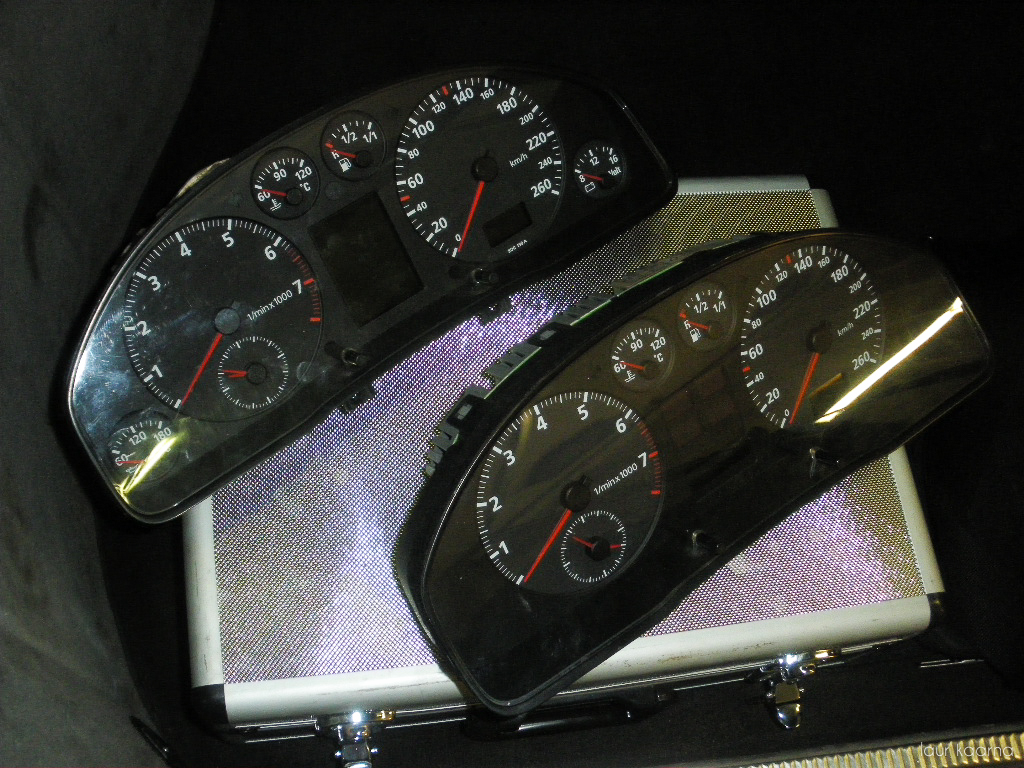
Ülemine: Audi A4 B5 täiskompuutriga näidikute plokk Alumine: Audi A4 B5 tavaline näidikute plokk
Vasakul on uued kellad ja paremal on vanad.
Järgnev DIY näitab kuidas täpselt sellist vahetust teha 97 aasta masinal. (st kelladel on üks sinine ja üks kollane pistik ning keskel üks väike must). Aastakäikude vahel on erinevusi ning ka kellasid on 3 v 4 erinevat. Pistikute klemmid võivad olla erinevad ja uuemate kellade puhul tekitab probleeme juba can-bus’i pealt juhtimine mida vanematel pole.
Mida on vaja?
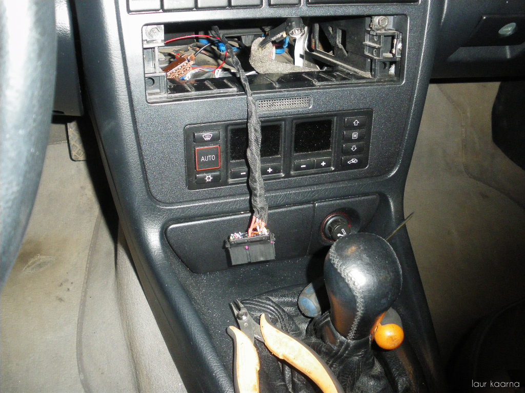
Alustama peaks kellade ploki eemaldamisest. Rooli peal on selline kaares kate, see käib lihtsalt tõmmates ära ja seal taga on 2 kruvi mis hoiavad plokki kinni. Seejärel lihtsalt välja tõmmata arvestades see juures et vasak pool tuleb rohkem väljapoole, paremal on lühemad juhtmed. Keerad vasaku poole välja ja saab kollase pistiku lahti võtta. (seal on üks lilla klõps, see tuleb eemale tõmmata näiteks kruvikeerajaga ajada ja päris välja tõmmata. alles siis tuleb pistik tõmmates välja).
Kui üks pistik lahti tuleb proovida plokk veits eemale tõmmata ja ka sinine pistik tagant võtta ning keskelt väike must. Katsetamise küsimus.
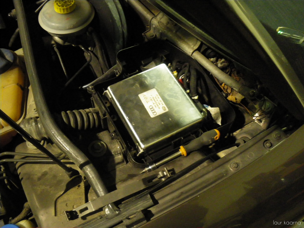
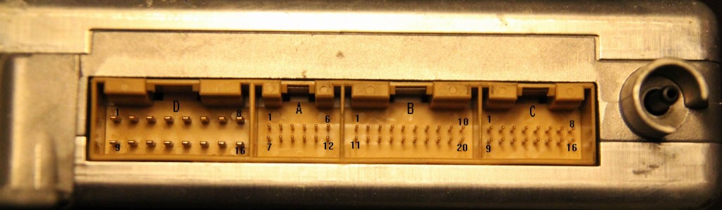
A4 B5 mootoriaju asukoht

Esimene juhe mida vedama hakata on ECU pealt küttekulu signaal. Selleks tuleb aju karp lahti keerata, klamber pealt lahti võtta ning siis saab juba punase pistiku tagant ära võtta. Pistik tuleb lahti võtta ning 8. klemmi peale üks juhe juurde joota. See juhe siis sealt samast aju karbist alla vedada, see auk läheb otse salongi kaitsmekarbi peale kuskile. Sealt hea kelladeni vedada.
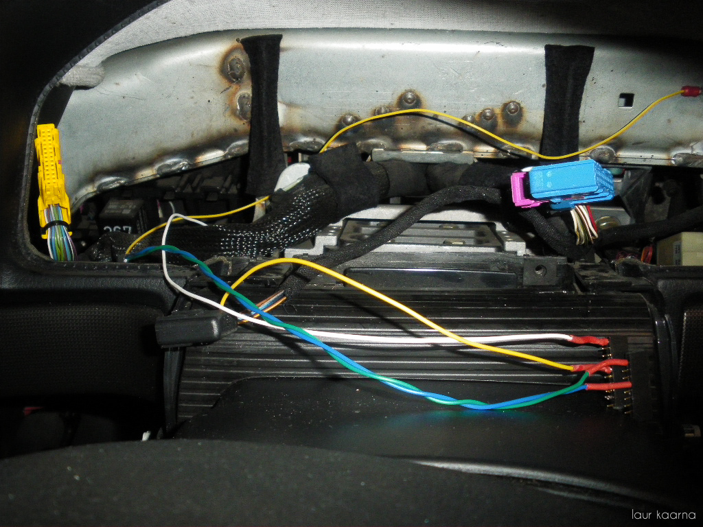
Klemmid nr. 16 ja 19 kellade ploki punses pistikus tuleb ühendada massiga. See kõrvaldab tulede ja piduri veateated. Pildil on need siis roheline ja sinine juhe mis on lõpus kokku joodetud ja sealt läheb edasi kollane juhe kere külge sest mul said kaablid kogematta liiga lühikesed 
Et saada välis temp. tööle tuleb vanast 10pin mustast pistikust vedada 4. klemmi pealt (pruun/kollane) juhe uue ploki punasesse pistikusse klemmi nr 5. külge.
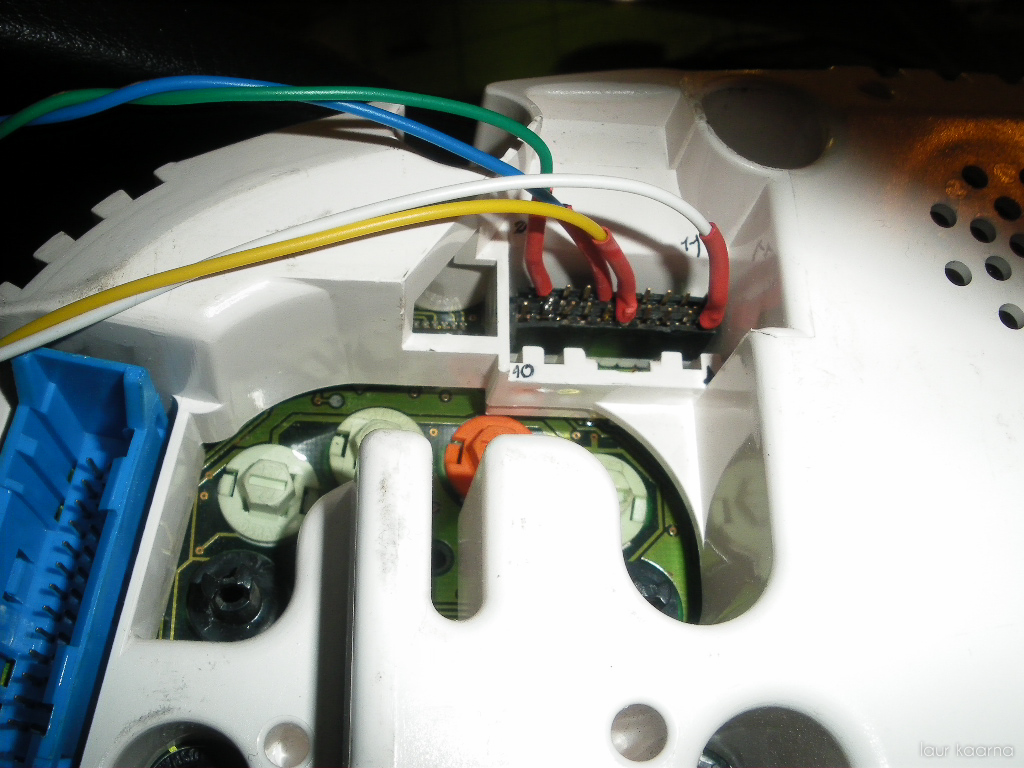
Pilt siis sellest kuidas asjad ühendatud on. Need klemmid sain ma oomipoest. 20 klemmi on seal reas tegelt, lõikasin rauasaega pooleks selle. Asja miinus on see et kui mõni klemm sealt üks kord välja tuleb siis ta hakkab maru kergelt välja käima. Ja üldiselt soovitatav oleks tellida uus pistik audist v kuskilt lammarist. Ise lähen ka kunagi seda teed.
Kui on originaal makk siis oleks tore ka maki infi saada ekraanile. Selleks tuleb vedada kolm juhet makini.
Raadiost info kuvamine täiskompuutril

Pistiku sain lammarist. Muidu maksab vist mingi 3-4€ esinduses + klemmid ka juurde. Vaja on keskmist pistikut kui esindusest tellid (oli vist roheline).
Pinout on juhendi lõpus olemas. Vaja siis clock signal, data signal ja enable signal. Enamasti on audi makkidel kleeps peal ja vastavate klemmide juures ka kiri mis asi see on. Niiet seda siin lahkama ei hakka, netis liigub pinoute ka piisavalt audi makkidele kui peaks keegi hätta jääma.
Lõpuks siis kogu pundar koos :

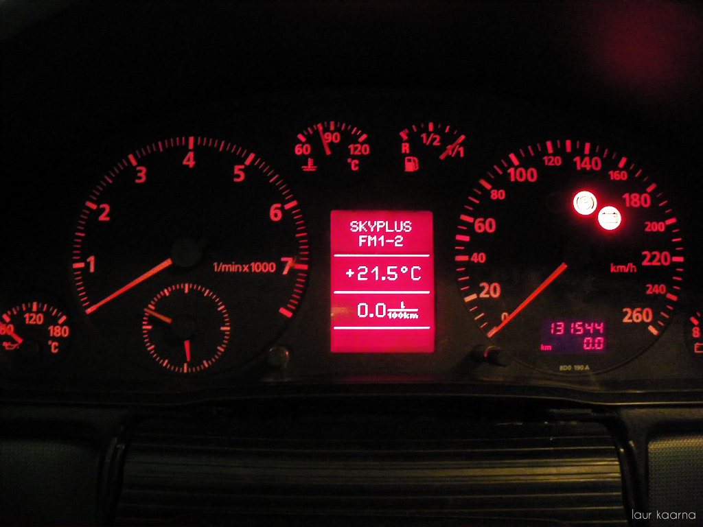
Toimiv täiskompuutriga näidikute plokk
Lõpetuseks tuleb uus kang paigaldada ja sealt 4 juhet vedada. Üks läheb massi ja 3 ülejäänud juhet tuleb järgnevalt ühendada numbrid on kojamehe kangi pistikul olemas).
mustal pistikul Pin 11 -> kojamehe kangil pin 4
mustal pistikul Pin 14 -> kojamehe kangil pin 2
mustal pistikul Pin 18 -> kojamehe kangil pin 1
Pin 3 kojamehe kangil läheb massi
Lõpetuseks üks hea link kus on enamus infot ja selgitusi: http://forums.audiworld.com/showthread.php?p=24085593
LISA 1
Pre 8/97 (This means you have a blue & a yellow connector on the back of your instrument cluster)
Pin 1 – Black/Red – Power
Pin 2 – Nothing
Pin 3 – Brown/Yellow – A/C Control Head (Outside Temperature)
Pin 4 – Grey/Blue or Grey/Yellow – Instrument Cluster Combination Processor (Pin 19 on blue connector)
Pin 5 – Nothing
Pin 6 – Brown – Ground
Pin 7 – White/Blue – Instrument Cluster Combination Processor (Pin 7 on yellow connector)
Pin 8 – Black/Brown – Transmission Control Module (Gear Indicator)
Pin 9 – Brown – Ground
Pin 10 – Nothing
Post 8/97 through to 99.5 (This means you have a blue & green connector on the back of your instrument cluster and an ANALOG clock)
Pin 1 – Black/Red – Power
Pin 2 – Nothing
Pin 3 – Nothing
Pin 4 – Grey/Blue or Grey/Yellow – Instrument Cluster Combination Processor (Pin 20 on blue connector)
Pin 5 – Nothing
Pin 6 – Brown – Ground
Pin 7 – Nothing
Pin 8 – Black/Brown – Transmission Control Module
Pin 9 – Nothing
Pin 10 – Brown/Yellow – A/C Control Head (Outside Temperature)
This connector does not exist on 2000+ models.
LISA 2
Spido 20pin. pistik (nö. kompu pistik):
Must, 20-pin connector for multi-function display
1 – Fuel consumption signal
2 – Open
3 – Open
4 – Open
5 – Outside air temperature
6 – Selector lever display
7 – Open
8 – Open
9 – Washer fluid
10 – Hydraulic pressure
11 – Trip computer reset
12 – Clock signal for radio frequency display
13 – Data signal for radio frequency display
14 – Trip computer (forward sequence)
15 – Enable signal for radio frequency display
16 – Tail lights/headlight low beam (indicator lights)
17 – Open
18 – Trip computer (reverse sequence)
19 – Brake lights
20 – Open
LISA 3
Kliimaautomaatik
Allikas
http://foorum.audiclub.ee/viewthread.php?tid=94753
Autor laur